A useful utility-pole inspection is not simply a collection of close-up photographs. It is a traceable record that connects each asset ID to repeatable views, visible conditions, and clearly stated limitations. For a newer commercial pilot, the safest approach is to agree on the inspection standard with the utility before launch, keep the aircraft inside an owner-approved operating envelope, and let qualified utility personnel decide what an observed condition means. This workflow shows how to plan, capture, organize, and report the imagery without overstating what a camera can prove.
This article is educational, not electrical, engineering, legal, or site-safety advice. The utility owner and qualified electrical personnel must establish site-specific controls. Never infer voltage or energized status from appearance.
Define the decision before choosing the flight
Start by asking what the client needs to decide. A vegetation-maintenance screen, storm-damage survey, attachment inventory, and detailed condition assessment are different assignments. They may require different viewpoints, image resolution, asset data, personnel, and escalation rules.
Turn the request into a written scope that identifies:
- the poles, structures, spans, or circuit segments included;
- the asset identifier and location source;
- the components or conditions the client wants documented;
- the required visible-light or thermal imagery;
- the expected ground sampling, image detail, or acceptance standard;
- the delivery format and naming convention;
- the party responsible for classifying urgency; and
- conditions that require the flight to stop or the finding to be escalated.
If the client asks for “an inspection” without defining those points, the pilot cannot know whether the deliverable is complete. Scope first; flight plan second.
Coordinate with the utility before entering the field
Utility infrastructure creates hazards that a normal aerial-photography checklist may not capture. Under OSHA’s electric-power standard, covered employers must address training, hazard information, job briefings, work procedures, special precautions, energy controls, and personal protective equipment. The standard also requires relevant characteristics—such as nominal voltage, line and equipment locations, pole condition, and environmental conditions—to be determined before covered work on or near lines begins.
That does not create a universal drone standoff distance. Instead, it reinforces why the host utility or controlling employer should define the operating area and communicate known hazards. Before mobilization, confirm the site contact, circuit or asset identifiers, access limits, nearby crews, switching or maintenance activity, traffic controls, public exposure, and the emergency communication path. A line that appears inactive must not be treated as de-energized.
When contractors and utility personnel share a site, document who owns the job briefing and how new information will reach the remote pilot in command. If field conditions differ from the briefing, pause and resolve the discrepancy.
Build the Part 107 plan around the infrastructure
The remote pilot in command remains responsible for the flight. The FAA’s preflight rule requires an assessment of the operating environment, including weather, airspace and flight restrictions, people and property on the surface, and other ground hazards. The pilot must also confirm that control links and available power are adequate for the planned operation.
For pole work, add these mission-specific questions:
- Can the aircraft remain in visual line of sight for every pole and span?
- Where can the crew launch without standing in traffic, vegetation, or a work zone?
- Could wind around structures or conductors reduce position stability?
- Are trees, guy wires, communications lines, transformers, fences, or uneven terrain harder to see from the launch point?
- What position or system behavior triggers an immediate retreat?
- Where is the predetermined safe landing area?
Electromagnetic or magnetic interference is possible around some infrastructure and equipment, but its presence and severity are site- and aircraft-dependent. Treat abnormal compass, positioning, telemetry, or control behavior as a reason to increase separation, change the plan, or land—not as something to “fly through.”
A visual observer can help watch the aircraft, airspace, obstructions, vehicles, and people, but does not transfer the remote pilot’s responsibility. Brief one clear communication method and avoid vague calls such as “watch out.”
Create an owner-approved operating envelope
Do not improvise how close to fly after arriving. Agree on an operating envelope that accounts for conductor movement, wind, aircraft stopping distance, navigation uncertainty, loss-link behavior, image resolution, and the client’s safety program. Use optical zoom or a higher-resolution payload to gain detail when appropriate, but remember that magnification cannot recover detail the sensor never captured.
Test the intended camera settings and distance on a non-energized reference or representative target when practical. The purpose is to confirm that the required hardware features are recognizable without moving the aircraft unnecessarily close to the infrastructure. Record the approved stand-off approach in the mission plan rather than presenting one number as safe for every voltage, structure, aircraft, and weather condition.
Use a repeatable utility-pole capture pattern
Consistency makes the imagery reviewable. A practical pattern for each pole can include:
- Context view: the complete pole, adjacent span, ground area, and nearby vegetation.
- Asset-ID view: a readable pole number or other identifier, when access and client policy allow.
- Four-side coverage: repeatable views from agreed quadrants, adjusted when access or hazards prevent a side.
- Top assembly: crossarms, insulators, conductors, braces, and attachment hardware visible from the approved envelope.
- Mid-pole attachments: transformers, switches, communications attachments, grounds, or other scoped components.
- Base and surroundings: pole-to-ground interface, obvious external damage, vegetation, erosion, and access conditions.
- Exception detail: one wider locating image followed by one or more detailed views of the observed condition.
The list is a starting point, not an engineering inspection specification. The utility should identify the components and views that matter for its asset class. If a required face cannot be captured safely, mark it as not observed instead of quietly omitting it.
Separate visible observations from conclusions
A photograph may show a cracked-looking insulator, displaced hardware, vegetation encroachment, corrosion-like discoloration, a leaning appearance, or external wood damage. It does not automatically establish electrical condition, remaining pole strength, internal decay, root cause, code compliance, or whether the asset is safe to operate.
Use neutral language tied to the image: “dark discoloration visible below the north crossarm in images P104-NE-03 and -04.” Avoid conclusions such as “failed insulator,” “unsafe pole,” or “imminent outage” unless a qualified person has made that determination and the report clearly attributes it.
Thermal imagery requires the same restraint. Apparent temperature patterns can be influenced by emissivity, reflected energy, viewing angle, weather, loading, distance, and camera settings. The thermal drone inspection guide explains why an anomaly is a reason for qualified follow-up, not a diagnosis by itself.
Control image quality in the field
Before leaving each asset, check focus, motion blur, exposure, glare, obstruction, and coverage. Use a shutter speed appropriate to aircraft and subject motion, keep sensitivity as low as practical, and avoid aggressive digital zoom. If the camera offers optical zoom, record the focal length or zoom setting so reviewers understand the field of view.
Capture the wide locating view before the detail view. Without context, a close-up may not tell the reviewer which side, component, or pole is shown. For repeat work, preserve the same viewpoint naming scheme and note unavoidable deviations. That discipline is also useful in roof inspections and other recurring asset programs.
Make every image traceable
Use a manifest rather than relying on camera filenames alone. A simple record can include project, date, pole ID, coordinates and coordinate source, viewpoint, image filename, sensor, operator, observed condition, and review status. One naming pattern might be:
PROJECT_POLEID_VIEW_SEQUENCE_YYYYMMDD
Do not imply coordinate accuracy beyond the method used. Consumer GNSS positions can help locate imagery, but they are not automatically survey control. Preserve original files and metadata, then make annotated copies for reporting so the source evidence remains intact.
Deliver an exception-focused report
A client-ready package commonly includes:
- an asset manifest showing captured, incomplete, and inaccessible poles;
- a contact sheet or structured gallery for each asset;
- annotated exception images that point to, but do not cover, the observed condition;
- the client’s own priority category when the contract authorizes its use;
- links between each observation and its original files;
- flight, access, weather, sensor, and visibility limitations; and
- a short list of assets requiring qualified review or another inspection method.
Keep “not observed,” “not visible,” and “no visible exception identified” separate. None means that the component has been proved defect-free. If you are pricing this as a new service, the first drone inspection quoting guide can help turn the capture standard and reporting workload into a defensible scope.
Know when to stop
Stop or reposition when the aircraft cannot remain in visual line of sight, wind or navigation behavior erodes the planned margin, people or vehicles enter the operating area, the field briefing no longer matches conditions, or the required image would demand leaving the approved envelope. Section 107.15 also requires the remote pilot to discontinue the flight if the aircraft is no longer in a condition for safe operation.
Never attempt to retrieve an aircraft from a pole, conductor, or utility-controlled area. Secure the public-facing area if possible, keep people away, and contact the utility through the agreed emergency path.
Utility-pole inspection field checklist
- Confirm scope, asset list, image standard, and acceptance criteria.
- Complete the host-utility briefing and record the site contact.
- Verify airspace, weather, access, traffic, people, and ground hazards.
- Set an owner-approved operating envelope and abort conditions.
- Brief crew roles, communications, loss link, and emergency actions.
- Capture context, ID, repeatable sides, hardware, base, and exceptions.
- Review focus, exposure, context, and completeness before moving on.
- Link every observation to the asset and original image files.
- State limitations and reserve diagnosis for qualified utility personnel.
- Deliver the manifest, images, exceptions, and follow-up list together.
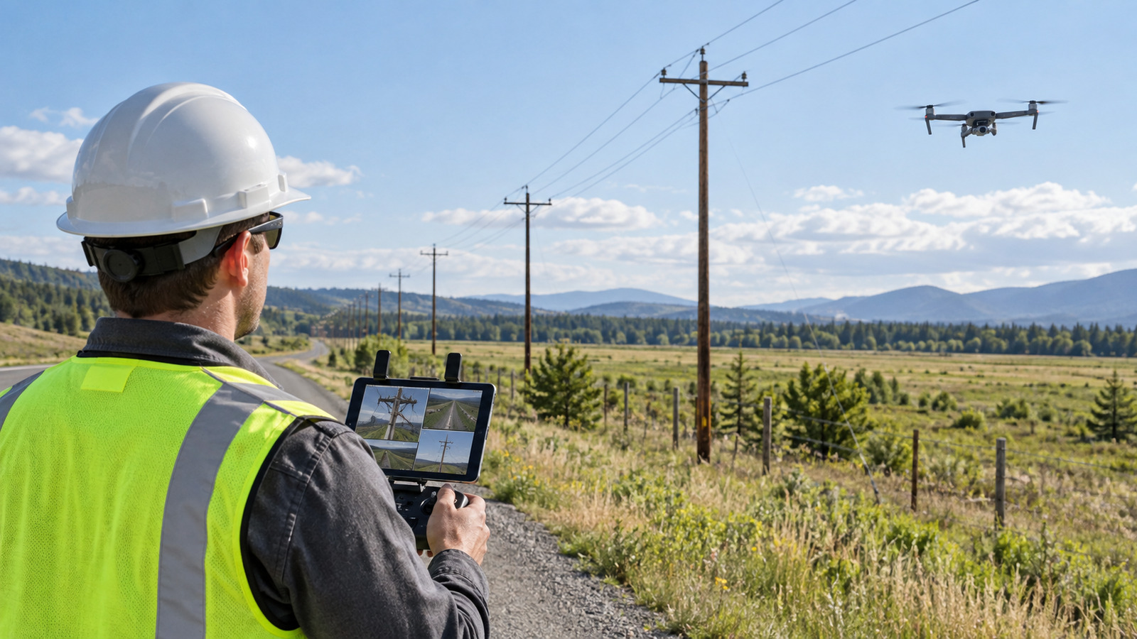
Sources: 14 CFR §107.15, §107.31, §107.49, and 29 CFR §1910.269, reviewed September 22, 2026. Featured image: original All About UAVs illustration; generic equipment and infrastructure, with no actual defect, measured project data, or energized-work condition depicted.